
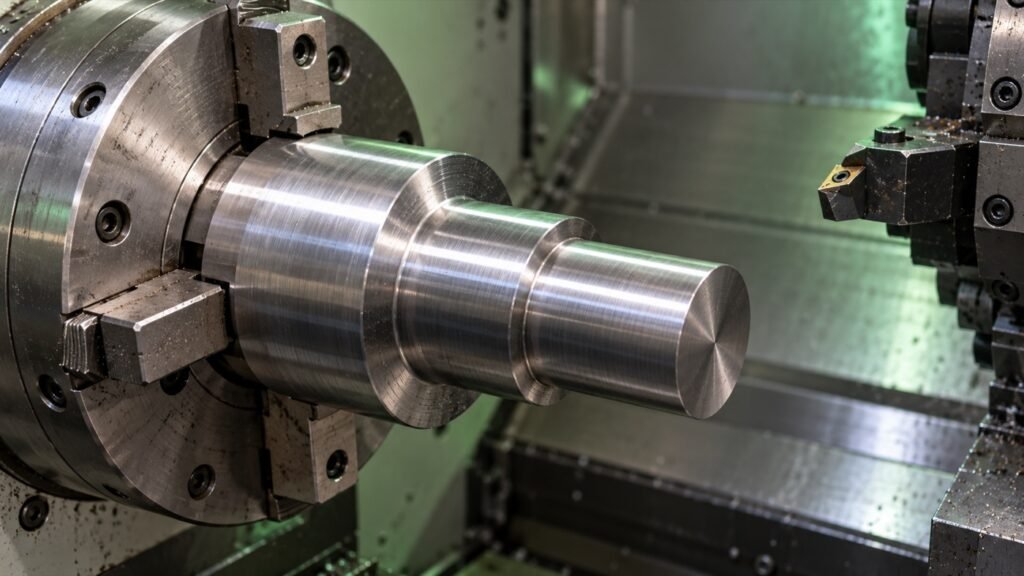
Constant surface speed changes spindle RPM as the cutting diameter changes. Fixed RPM keeps spindle revolutions steady, so the surface speed changes with diameter instead. This distinction matters when facing a part, turning stepped diameters or estimating cutting time.
This guide explains the geometry with inch and metric examples. G96, G97 and G50 references below describe Haas lathe documentation; check the programming manual for your own machine before applying control commands. The example speeds are arithmetic inputs, not cutting recommendations.
Constant surface speed vs fixed RPM
Surface speed is how far the circumference passes the cutting edge in one minute. A larger diameter travels farther per revolution. Under fixed RPM, moving to a smaller cutting diameter therefore reduces the surface speed. Under constant surface speed, the control increases RPM as diameter decreases, until a configured speed limit or other machine constraint prevents further increase.
Haas documents G96 as constant surface speed on and G97 as constant surface speed off. Its G50 command sets a maximum spindle speed. These are distinct jobs: the surface-speed command sets a target, while the RPM limit bounds the resulting spindle speed.
RPM formulas for inches and millimetres
For a diameter D in inches and a surface speed V in feet per minute: RPM = 12 × V ÷ (π × D). For D in millimetres and V in metres per minute: RPM = 1000 × V ÷ (π × D). The factors 12 and 1000 convert the surface-speed length units into the diameter units.
The reverse equations are V = π × D × RPM ÷ 12 for feet per minute, or V = π × D × RPM ÷ 1000 for metres per minute. Always use the diameter where the tool is cutting, rather than a different step on the part. Try the lathe RPM and feed calculator to compare diameters.
Inch example: 400 SFM at two diameters
At a 2-inch cutting diameter and a target of 400 feet per minute, theoretical RPM is 12 × 400 ÷ (π × 2) = approximately 764 RPM. At a 1-inch diameter, maintaining the same target requires approximately 1,528 RPM. Halving the diameter doubles the theoretical RPM.
If the spindle instead stays at the unrounded first RPM, the 1-inch diameter has a surface speed of 200 feet per minute. That is the fixed-RPM tradeoff: unchanged revolutions, but a different speed at the cutting edge.
Metric example: what an RPM limit changes
At 150 metres per minute and a 50 mm diameter, the theoretical speed is approximately 955 RPM. At 25 mm, it is approximately 1,910 RPM. Suppose a hypothetical setup has a 1,200 RPM limit. At 25 mm the speed is then capped at 1,200 RPM, giving an actual surface speed of π × 25 × 1,200 ÷ 1000 = approximately 94.2 metres per minute.
The cap begins to matter below D = 1000 × 150 ÷ (π × 1,200), or approximately 39.8 mm. Above that diameter, the target requires less than 1,200 RPM. Below it, the theoretical requirement exceeds the cap. The 1,200 RPM value here illustrates the calculation; it is not a safe limit for any particular chuck or workpiece.
Why facing toward centre needs an RPM limit
The theoretical equation divides by diameter. As diameter approaches zero, the calculated RPM rises without bound; no real spindle can follow it to zero diameter. Haas explicitly warns that constant surface speed needs a maximum spindle RPM setting. Choose the permissible limit from the actual machine, chuck, jaws, workholding and workpiece conditions—not from this example.
How the choice affects feed and cycle time
With feed specified per revolution, linear feed per minute equals RPM multiplied by feed per revolution. At 0.010 inch per revolution, 764 RPM gives about 7.64 inches per minute, while 1,528 RPM gives about 15.28 inches per minute. This relationship does not mean a surface-speed target automatically sets the correct chip load: feed remains a separate machining decision.
A constant-RPM straight pass can use cutting time = travel ÷ linear feed. A facing pass under constant surface speed has changing RPM and potentially changing linear feed, so one fixed-RPM calculation is only an approximation. For rough planning, use the lathe cycle-time estimator, then compare its assumptions with the actual process. The lathe cycle-time formula guide separates cutting, non-cutting and batch setup time.
Common questions
Is constant surface speed the same as constant feed?
No. Constant surface speed targets speed at the cutting circumference. Feed per revolution or feed per minute describes tool advance and must be considered separately.
Does constant surface speed keep RPM constant?
No. RPM changes when cutting diameter changes, unless it is constrained by a limit. Fixed RPM keeps revolutions steady instead.
Can I copy the example RPM limit into my program?
No. The hypothetical limit only demonstrates the math. Determine a permissible RPM from your machine and workholding documentation, actual setup and approved shop procedure.
Manufacturer references
Put the formulas to work
Use our free calculators for speeds, feeds, angles, hole patterns and dimensional checks. For content corrections, contact CNC TrueCut.
Tooling and insert brands: discuss an advertising partnership.