
Turning insert guide: shapes, materials and applications
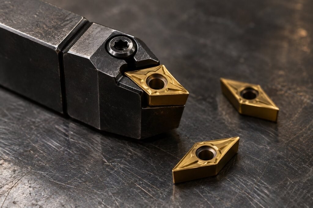
Choose the shape for the cut, then select a compatible grade and chipbreaker for the exact material. CNMG, DNMG and VNMG are shape families, not material grades.
Compare the shapes
| Shape | Point angle | What to review |
|---|---|---|
| CNMG | 80° | Outside turning and roughing candidates; confirm access around shoulders. |
| DNMG | 55° | Profile access with more point support than a 35° shape. |
| VNMG | 35° | Narrow-profile access; review the available edge support and holder clearance. |
These inserts require compatible holders. The table lists nominal point angles. Confirm holder clearance and the planned toolpath separately; the image is illustrative.
Material first, exact grade next
Identify the alloy, condition and hardness. Use P, M, K, N, S or H as a catalogue filter, then check the toolmaker’s material subgroup. Do not use the shape letters as a substitute for a grade recommendation.
Build your selection sheet
- Write the part’s material and heat-treatment condition.
- List the surfaces and operation: roughing, finishing or profiling.
- Confirm the holder and full insert size.
- Record the supplier’s grade, chipbreaker and nose radius.
- Attach the recommended speed, feed and depth-of-cut range.
- Calculate RPM and feed, then record the approved setup and inspection.
Read the insert guides
CNMG vs DNMG vs VNMG: Which Turning Insert Shape?
Choose a Turning Insert Grade by Workpiece Material
Turning Insert Setup Checklist: Holder, Radius and Chipbreaker
Calculate turning RPM and feed → · Material reference
Sources
Sandvik Coromant turning insert selection · Workpiece material classification