
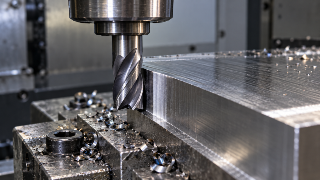
The radial chip thinning formula estimates the feed per tooth needed to maintain a target maximum chip thickness during light side milling. For radial engagement below half the cutter diameter, use fz = h ÷ √[4r(1 − r)], where r = ae/D.
The distinction matters: programmed feed per tooth and maximum chip thickness are different quantities. This guide shows the calculation with a simple inch example and explains when the multiplier should stay out of your program.
What radial chip thinning means
In conventional peripheral milling, chip thickness changes as each tooth passes through the cut. At light radial engagement, the cutting edge does not pass through the position that produces the maximum thickness associated with the programmed feed per tooth.
Harvey Performance’s chip-thinning explanation identifies radial depths below 50% of cutter diameter as the region where maximum chip thickness decreases. That does not automatically authorize increasing feed: the tool and setup still impose limits.
Radial chip thinning formula and symbols
For an ideal cylindrical cutter with a 90° entering angle in steady side milling:
r = ae / D
Chip-thinning factor K = 1 / √[4r(1 − r)]
Adjusted feed per tooth fz = target maximum chip thickness h × K
D is cutter diameter; ae is radial width of cut, often called stepover. Use the same units for both. The ratio r has no unit. The calculated fz uses the same length-per-tooth unit as h.
This low-engagement expression applies for 0 < r < 0.5. At 50% engagement, K = 1. For ordinary radial chip-thinning compensation at 50% engagement or above, use K = 1 rather than extending the low-engagement expression into slotting. At zero engagement there is no cut and the expression is undefined.
Worked example: a half-inch end mill at 10% engagement
Consider a 0.500 in diameter cutter taking a 0.050 in radial cut. Assume a target maximum chip thickness of 0.002 in, four effective cutting teeth, and 6,000 RPM. These are illustrative inputs, not cutting-data recommendations for a material.
First, r = 0.050 / 0.500 = 0.10. Then √[4 × 0.10 × 0.90] = 0.60, so K = 1 / 0.60 = 1.6667. The adjusted feed per tooth is 0.002 × 1.6667 = 0.003333 in/tooth.
Calculate table feed from F = RPM × effective teeth × fz. Here F = 6,000 × 4 × 0.003333 ≈ 80 in/min. Using 0.002 in/tooth without compensation would give 48 in/min and an ideal maximum chip thickness of 0.0012 in at this engagement.
Sandvik Coromant’s milling formulas define the relationship between table feed, spindle speed, effective cutting teeth and feed per tooth. The formula converts your chosen inputs; it does not establish a suitable target chip thickness.
Quick multiplier comparison
| Radial engagement ae/D | Ideal factor K | fz for h = 0.002 in |
|---|---|---|
| 5% | 2.2942 | 0.004588 in/tooth |
| 10% | 1.6667 | 0.003333 in/tooth |
| 20% | 1.2500 | 0.002500 in/tooth |
| 50% | 1.0000 | 0.002000 in/tooth |
The rapidly rising factor at very small engagement is a reason to check machine and tool limits, not a reason to command an unlimited feed.
Do not compensate twice
Before applying K, check what the manufacturer’s recommendation represents. A feed-per-tooth value already specified for your radial engagement may already include the adjustment. Likewise, a CAM cutting-data feature may calculate a compensated feed.
Record whether the starting value is a target chip thickness, a baseline feed at 50% engagement, or an already adjusted feed. If the source is unclear, ask the supplier before multiplying. Keep the source value and your calculation together in the setup notes.
Where the simple model stops
This equation does not account for tool runout, deflection, chip evacuation, machine acceleration, or changing engagement in corners. Ball-nose tools, round inserts and cutters with other entering angles need geometry-specific calculations. A narrow nominal stepover also does not guarantee low engagement throughout the entire toolpath.
Use the toolmaker’s limits for the exact cutter, material, axial depth and overhang. Check entry moves and corners in CAM, and validate the setup before relying on an adjusted feed. A mathematical chip-thinning factor cannot correct a toolpath that overloads the cutter.
Use the free chip-thinning calculator
Enter diameter, radial engagement and target chip thickness in our radial chip-thinning calculator. Then use the milling speeds and feeds calculator to check RPM and table feed. The unit converter helps keep inch and metric source data consistent.
Common questions
Is 10% engagement entered as 10 or 0.10?
In the formula, r is a ratio: enter 0.10. If a calculator asks for a percentage, follow its label and enter 10. If it asks for radial width, enter the actual ae dimension.
Does chip thinning change the RPM formula?
No. This calculation adjusts feed per tooth for radial engagement. Choose cutting speed and calculate RPM separately for the cutter and workpiece.
Put the formulas to work
Use our free calculators for speeds, feeds, angles, hole patterns and dimensional checks. For content corrections, contact CNC TrueCut.
Tooling and insert brands: discuss an advertising partnership.